Is Higher Porosity Always Better for a Electrolyzer PTL
Porosity is one of the first specifications engineers examine when selecting a porous transport layer for a PEM water electrolyzer. The logic appears straightforward: a more open structure should make it easier for water to reach the anode catalyst layer and for oxygen to leave the reaction zone. In practice, however, PTL performance is determined by more than the amount of empty space inside the material.
The PTL must perform several functions at the same time. It transports liquid water and oxygen, conducts electrons and heat, supports the catalyst-coated membrane, and maintains stable contact under assembly compression and differential pressure. Improving one function can weaken another. This is why the PTL with the highest porosity is not automatically the PTL that gives the lowest cell voltage or the best long-term stability.
What a PEM electrolyzer actually requires from the PTL
At the anode, water passes from the flow field through the titanium PTL to the catalyst layer. Oxygen generated by the oxygen evolution reaction must travel in the opposite direction without blocking water access to active sites. At the same time, electrons must move efficiently from the catalyst layer through the PTL to the bipolar plate.
These transport functions are closely coupled. A very dense structure may provide many electrical contact points but restrict liquid and gas movement. A very open structure may improve permeability but provide insufficient solid contact with the catalyst layer. The PTL therefore needs both effective pore pathways and an effective solid network.
Its surface is just as important as its bulk. The catalyst layer is thin and has limited in-plane electrical conductivity. Areas that are poorly connected to the PTL may contribute less effectively to the reaction, even when the PTL itself has excellent permeability. The result can be higher constriction resistance, uneven current distribution and reduced catalyst utilization.
Titanium felt offers open transport pathways
Titanium felt is formed from randomly arranged titanium fibers that are bonded into a porous network. This architecture can offer high void volume, interconnected pathways and relatively low resistance to gas movement. These characteristics make titanium felt attractive when rapid oxygen removal and water distribution are priorities.
The same fibrous structure can also create challenges at the catalyst-layer interface. Individual fibers contact the catalyst layer along narrow lines or at discrete points. Fiber intersections, cut ends and local thickness variation may increase surface roughness. As a result, the real electrical contact area can be much smaller than the apparent geometric area.
Compression can improve contact, but excessive compression may deform the felt, change its pore structure or transfer concentrated loads to the CCM. These effects become more important in high-pressure operation, where the membrane can be pushed toward the anode PTL. Larger surface openings and local asperities may allow deeper membrane intrusion or create stress concentrations in the catalyst layer.
Titanium felt is therefore not defined only by high porosity. Fiber diameter, fiber orientation, surface finish, thickness consistency, compressibility and coating quality all influence its cell-level behavior.
Sintered porous titanium creates a more controlled interface
Sintered porous titanium is usually produced by consolidating titanium particles into a connected metallic structure while preserving a designed pore network. By adjusting powder characteristics and processing conditions, manufacturers can tune pore size distribution, porosity, thickness and surface morphology.
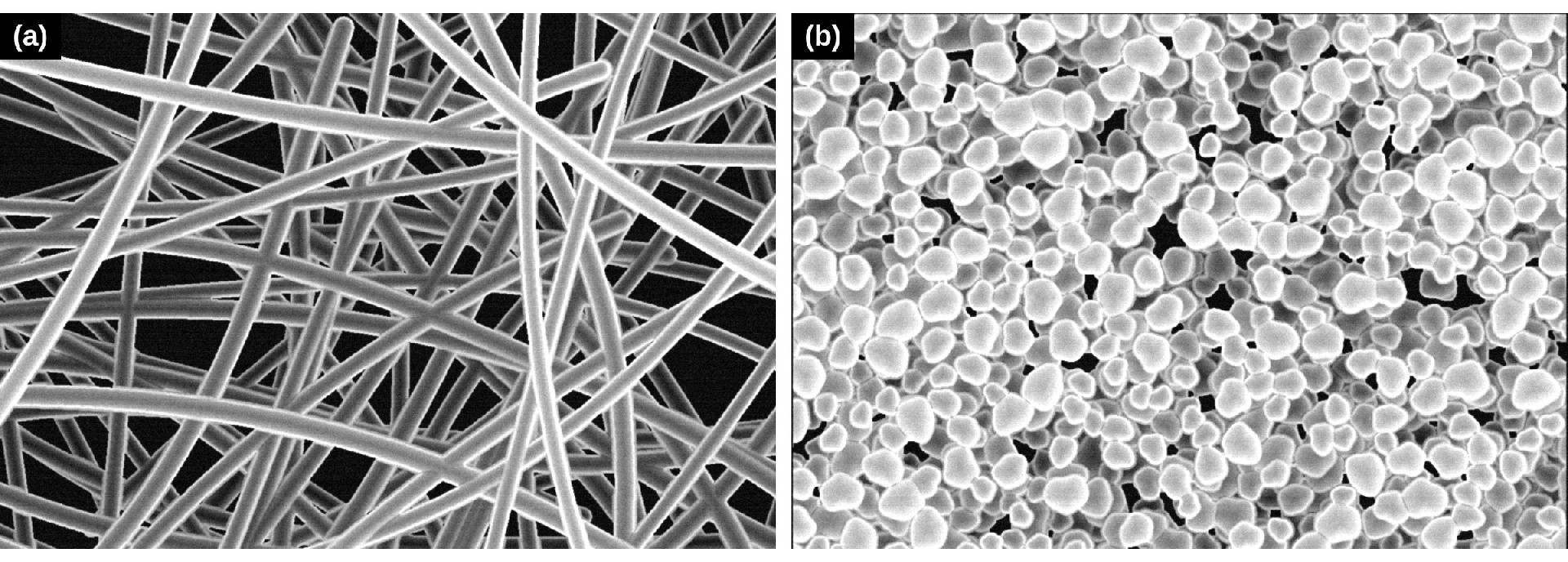
Figure 1. Representative SEM-style top views of (a) titanium felt and (b) sintered porous titanium. Schematic illustration, not actual micrographs.
Compared with a random fiber surface, a particle-based porous structure can provide a finer and more continuous contact face. More contact points can reduce the distance electrons must travel laterally through the catalyst layer before reaching the PTL. This can lower interfacial and constriction losses and help a larger fraction of the catalyst layer participate effectively.
A smoother surface also distributes assembly pressure over a larger area. This may reduce localized indentation of the catalyst layer and membrane, which is particularly relevant for thinner membranes, lower catalyst loadings and differential-pressure operation. Better distributed contact also supports heat transfer and can reduce local thermal or current-density gradients.
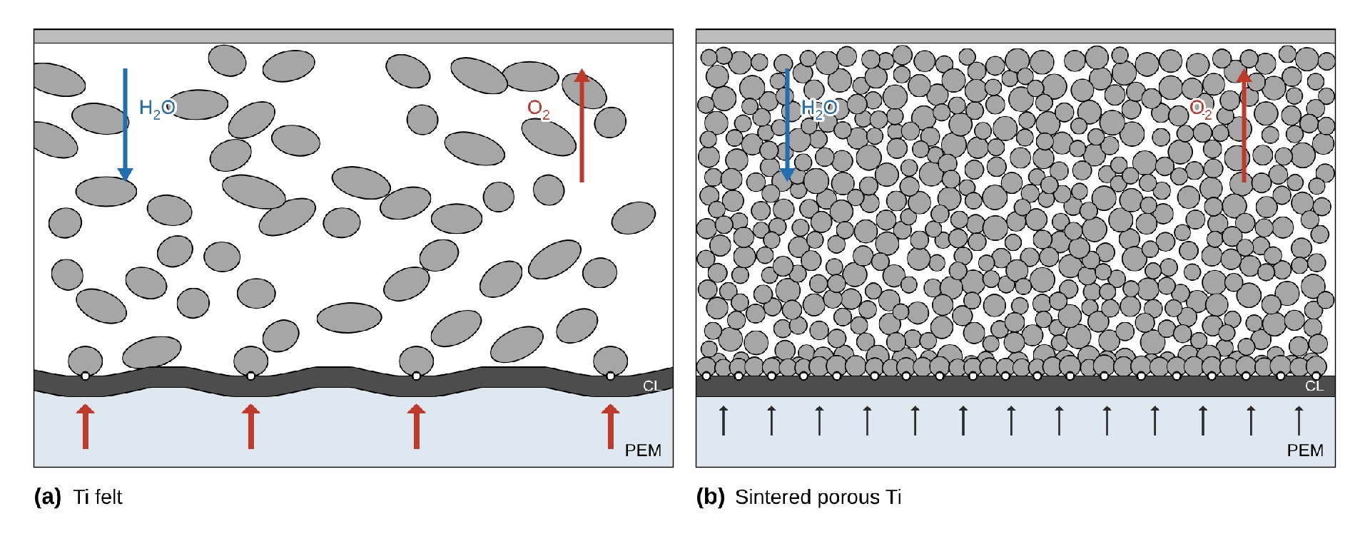
Figure 2. Schematic cross-sections of the anode PTL/catalyst layer (CL) interface under compression for (a) Ti felt and (b) sintered porous Ti. Open circles mark electrical contact points; arrows beneath the CL indicate local load on the membrane. Not to scale.
These advantages do not make every sintered porous titanium structure superior to every titanium felt. A porous plate with insufficient permeability, poorly connected pores or excessive thickness can introduce its own losses. The benefit comes from controlling both the bulk transport structure and the surface that touches the catalyst layer.
Why porosity alone can be misleading
Two PTLs with the same nominal porosity can perform differently because their pores are not arranged in the same way. Pore diameter, throat size, tortuosity, pore connectivity and through-plane orientation determine how easily water and oxygen move. Surface pore openings determine how the bulk structure communicates with the catalyst layer.
The solid phase is equally important. Particle or fiber size affects electrical pathways, contact density and mechanical support. Thickness influences both resistance and transport distance. Surface oxide and coating condition influence interfacial contact resistance. Compression changes nearly all of these relationships during cell assembly.
For this reason, porosity should be evaluated together with:
Pore-size distribution and pore connectivity
Through-plane permeability and two-phase transport behavior
PTL–catalyst interfacial contact area
Surface roughness and local protrusions
Electrical and thermal contact resistance
Thickness, strength and compression response
Operating current density and pressure
Catalyst loading, membrane thickness and coating system
The relevant question is not “How porous is the PTL?” but “Does this pore structure support the required transport while maintaining enough contact and mechanical protection at the operating point?”
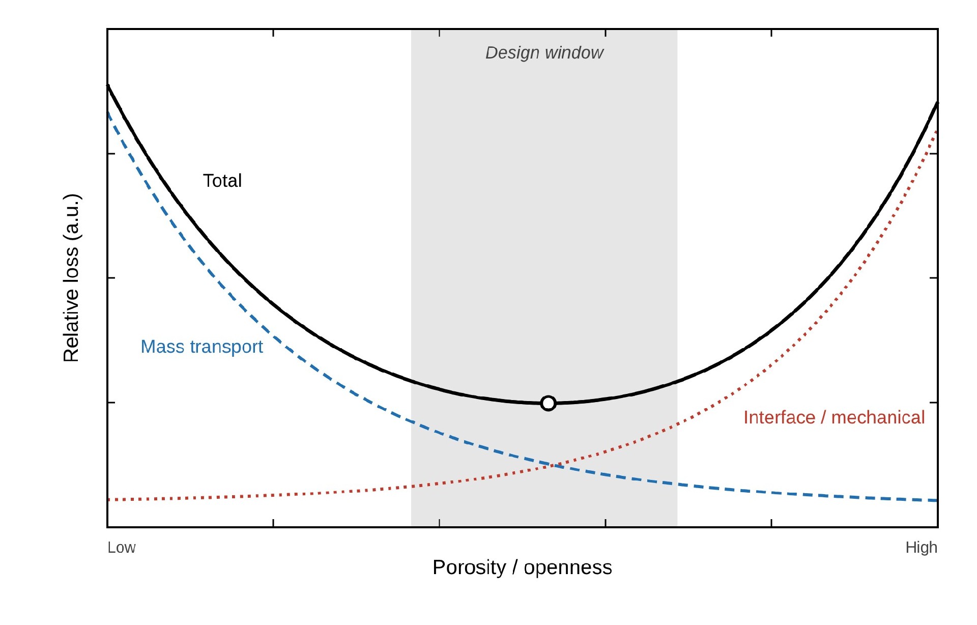
Figure 3. Conceptual relationship between PTL porosity and cell-level loss. The total loss (solid) combines mass-transport loss (dashed) and interface/mechanical loss (dotted); the shaded region marks the design window. Not a quantitative performance curve.
The interface becomes more important as electrolyzers evolve
Efforts to reduce iridium loading and membrane thickness make PTL design increasingly important. With less catalyst, losing contact with even a small region of the catalyst layer can have a larger effect on utilization. With a thinner membrane, local deformation and pressure concentration become more critical. At higher current density, water supply, oxygen evacuation, heat removal and current distribution all need to remain stable at the same time.
Recent PTL development therefore focuses on hierarchical and graded structures rather than maximizing one bulk property. A fine structure near the catalyst can improve contact and protect the CCM, while a more open backing structure can support rapid transport toward the flow field. This same design logic explains the growing interest in microporous layers, graded porous titanium and composite PTLs.
When porous titanium can be the better choice
Sintered porous titanium is especially attractive when the application requires a smooth and repeatable interface, controlled pore openings, uniform compression support or operation with thin membranes and low catalyst loading. It can also offer advantages where dimensional stability and reproducible large-area contact are important for stack assembly.
Titanium felt may remain a strong option when low bulk transport resistance, flexibility or specific compression behavior is the main priority. In many systems, the best solution is not a simple choice between the two. A multilayer or composite architecture can combine a fine porous titanium layer at the catalyst side with a more open support layer toward the bipolar plate.
The selection should ultimately be based on electrochemical performance, pressure conditions, coating requirements, manufacturing tolerances and long-term durability, not on porosity in isolation.
YIANTENG’s approach to PTL development
YIANTENG works with electrolyzer manufacturers to match porous titanium structure and surface condition to the requirements of the cell. The objective is to balance water and oxygen transport with electrical contact, mechanical support and coating durability.
This means considering the complete component rather than a single headline parameter: the pore network inside the PTL, the surface touching the catalyst layer, the side contacting the bipolar plate, the coating system and the compression conditions used in the stack.
Founded in 1993, YIANTENG has 33 years of experience in electrode and coating technologies. Our team supports technical discussions from material selection and sample evaluation to customized PTL and coating solutions.